Hello,
Is there any way to know at what battery level the module is when it’s ran on external battery?
Hello,
Is there any way to know at what battery level the module is when it’s ran on external battery?
Hi Ytung,
If you want to measure current draw on the Development Kit, please desolder the resistor R6 and connect your current meter to the TP_M1 and TP_M2 pins of the PCB. Also please place the “Vbackup” and “Power” jumpers to the right side marked as “battery” so you are actually connected to the battery.
In case you are interested how to measure battery voltage on your own project, I can also help you with that.
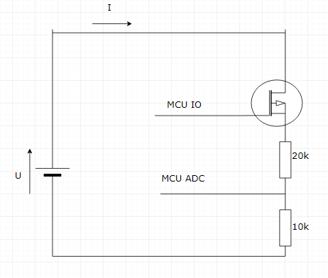
The best way to know what voltage your battery is, is by connecting it to an ADC. However, connecting it directly, might not be optimal if you are using higher voltage levels than maximum permitted.
In that case you can use a resistor divider. Since the ADC best operates with the internal voltage reference of 1.2V, that would be the maximum voltage allowed. If measuring a coin cell, the resistor ratio should be 3:1 or 20kOhms + 10kOhms. Take note that with higher resistances there is less current draw.
The resistor divider will draw 100uA, which might not be perfect for battery powered application as it will discharge the battery further. Placing a MOSFET in series with the resistor divider, and turning it on just when you need to measure the voltage and turning it off in the meanwhile is a good solution.
Be advised that the current version of the stack which was sent on the development kits, still does not have the low power mode so the current consumption might be a bit higher than expected. This will be fixed in the next update.
Hope that helps
Tom
ok thank you! btw one more question, I noticed that on the module some of those GPIO have the same number pin. For example there are 2 p10.0, are these the same pins?
Hi Ytung,
Yes, these are the same pins. The module has 12 GPIOs and to make it compatible with Arduino shields, we needed to use the same pin on multiple locations.
Tom