I have decided, late in the design process, to add BLE functionality to my project, so I need to think about antennas.
I don’t have enough PCB space for any of the common microstrip designs and I don’t have enough vertical space for a 1/4 wave monopole. I could snake a 1/4 wave wire around the enclosure, but I know that if I do that, it will no longer be 1/4 wavelength electrically.
Everything I have read on Bluetooth antenna design focuses on efficiency and range. I don’t really need either. I would be happy if I could get consistent communication at 1 or 2 meters distance.
Has anybody used BLE on the Onethinx module with a random wire antenna (or no antenna)? If so, do you think I could get the minimal performance that I need?
I do not have a lot of knowledge in antenna design. What I can suggest is a small chip antenna from Fractus. The antenna on our DevKit is from this manufacturer as well. We are very satisfied with this manufacturer. This antenna size is only 4.1 mm x 2.0 mm x 1.0 mm and it supports minimal clearance of 7.5 mm x 5 mm.
What you can do as well is: either connect a 50 ohm resistor directly to the Bluetooth pin on the module (Between the bluetooth pin and ground). That might be a short range solution for bluetooth. because at the pin of the ble on psoc, the network is matched for 50 ohms, adding 50ohms to ground will make an “antenna”
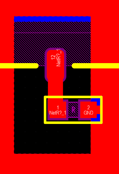
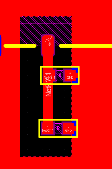
If that first solution proves to be to short range, you can put a 5mm line with a possibility to connect a resistor both at the begging and the end of the line. And the experiment with resistors. example below:
Some additional info: we noticed BLE works well even without antenna connected. It’s however not good practice to leave the BLE PA unloaded (RF waves will get reflected back into the PA which may cause overloading and/or spurious emissions). Therefor a small trace as Tomislav suggested in combination with a termination resistor will be the best solution. The resistor has to be specified for 2.4GHz in such a way that the mismatch will not be too high (preferably has an SWR of < 5).
It sounds like I need either a chip antenna or a leaky (radiating) dummy load.
I had originally ruled out chip antennas because every application guide I’ve seen requires the chip to be placed at the edge of the PCB, which was already occupied. However, I am now attempting to free up some space between the antenna pin and the PCB edge, so I can still have that option.
I have another idea. It’s been a long time (~ 30 years) since I played with RF (and I never ventured into microwaves), so I don’t know if my reasoning is sound, but here goes. I wonder if a string of resistors (say, 5 x 10 Ohm ) in series might result in a very low Q (wide bandwidth, but high loss) antenna.